Pictures and Diagrams
Pictures and diagrams are vital for modern documentation. They spare you the trouble of reading through long, wordy, never-ending, intimidating, and monotonous chunks of text. In today’s fast-paced world, a proper illustration or infographic can save the reader a lot of time, as a visual communicates information not only in a more efficient and less time-consuming but also in a more attractive and engaging way.
Illustrations bring more air to a document structure and work like magnets impelling the reader to glide through the preceding text and reach the reward in the form of an engaging illustration. They can be compared to rest areas on a highway.
Please have a look at the diagram in the following figure. Now imagine how many words the description of the continuous testing process will require. Still, this textual description will not be as clear and informative as the diagram.
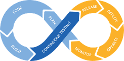
Continuous Testing
However, the above arguments do not imply that you should use lots of unnecessary illustrations. On the contrary, visuals in technical documentation must contain only relevant information to avoid misleading the reader. Every pixel must be meaningful and insightful.
This chapter starts with the description of terminology and then provides the guidelines for creation and placement of pictures and diagrams in Espressif’s documentation.
The sections primarily concentrate on illustrations for getting started guides but also touch upon other types of documents. In any case, most of this information can already be used for the majority of Espressif documents.
Terminology
For the purpose of disambiguation, this section defines the terms used in this chapter to denote pictorial illustrations and their parts.
Image is a picture or diagram intended for placement into a document.
Figure is any image included in a document and is usually mentioned or referred to in a surrounding text. Figures can have numbers and captions. Figures do not include tables.
Photo is a raw image taken with a camera and stored in memory as a computer file. The term photo may also denote a computer file itself.
Picture is a processed photo. It usually contains callouts and other information. It can also include a key.
Diagram is an illustration drawn manually or generated by a computer program. It usually contains callouts and a key.
Caption is the explanatory text that is placed immediately below a figure. It usually consists of one line – a title, which may also be followed by a paragraph with additional information. This paragraph must have distinctive formatting to avoid confusion with body text.
Callout is a label with a leader line that provides textual information about a part of a picture or diagram.
Key identifies the symbols used in an image and usually appears within an image.
To visualize how the provided terms are related, please check the following figure.
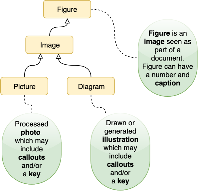
Terminology Tree
Taking and Processing Photos
To include a picture of a piece of hardware in a document, you need to obtain professional and consistently looking photographs. You can turn to Espressif Graphics team to take pictures for you, or you can do it on your own.
The sub-sections below provide general guidelines and best practices for taking photographs to standardize the process.
Taking Photos
Practices to avoid:
Avoid taking shots with a phone camera from a close distance. It leads to perspective distortions. A tell-tale sign of this is diverging pin headers on a board, which normally should look parallel to each other.
Do not take photos on a table lit with standard overhead office lighting. The consequences of that are distracting background color and texture, as well as dark-gray shadows. The resulting image usually looks amateurish.
Make sure the board is free from dust and fingerprints, and flux residue.
Practices to follow:
Use a light tent, a.k.a. a light box. You can buy it or create your own. It only takes a few pieces of paper folded in a proper way and a couple of lamps.
Use the resolution of no less than 600 dpi to allow for cutting out closeups in case some minute components would need to be documented later.
Choose angles that reveal important components or relevant features of a product. If possible, try to keep to similar angles across products for consistency of style. Usually, the following angles are required:
Isometric view (three dimensional view)
Front view
Back view
Side view
Examples of pictures can be found in ESP32-S2-Kaluga-1 Kit Getting Started Guide.
Once the photos are taken, do the following:
Obtain the files by copying them from your camera.
Rename the files in accordance with Section Naming Conventions.
Archive raw photos in accordance with Section File Storage Locations.
Processing Photos
Now the raw photos need to be processed and reduced in size.
You might also need to cut out closeup views of certain areas of a board from the raw image, for example, some jumper blocks or resistors.
For this:
Make background of the photo transparent to avoid issues when inserting this photo into a document with a non-matching background color.
Crop unwanted outer areas leaving a small margin or cut out the areas for close-ups.
Downscale depending on the requirements for your target document. See Section Publishing Checklist.
Save to PNG with the option transparent background turned on. The PNG format is good for compressing regular geometrical shapes, text, and straight lines. This is exactly what you can find in pictures of boards, other hardware, and user interface screenshots.
When the photo is processed, do the following:
Name it in accordance with Naming Conventions.
Save to PNG and then:
If the image needs to be annotated, go to Section Annotating Images. Compressed images requiring annotations do not need to be archived as they will be stored in source files with annotations.
If it is a cut-out closeup, archive it in accordance with Section File Storage Locations, then place it into your target reST file in accordance with Section Placement in a Document.
Annotating Images
Please use LibreOffice Draw for preparing annotated images. Import your compressed photo into LibreOffice Draw and add callouts. Follow the established style for your type of document.
Preparing Diagrams
This section briefly overviews the tools used at Espressif and then provides the workflow for each tool.
Software Overview
The tools recommended for use are listed below in the highest to lowest priority order:
Blockdiag is an extension bundled with Sphinx that allows you to “write” different kinds of diagrams as code using a simple markup language. Creating diagrams with blockdiag is similar to developing documentation with Markdown and reStructuredText. This tool is versatile but somewhat limited in its functionality.
Draw.io is an online tool for creating all kinds of diagrams. The tool provides more freedom than blockdiag but has no integration with Sphinx.
LibreOffice Draw is an application from the LibreOffice suite, which provides a lot of freedom in creation of diagrams.
Blockdiag
A big advantage of diagram generation tools, such as blockdiag suite, is the fact that the diagrams created with them are essentially computer code. It means that such diagram files occupy much less memory space than pictures and allow for more transparent version control.
The table below shows all the diagram types supported by blockdiag suite.
Diagram Type |
Sphinx Directive |
|---|---|
Block diagram |
|
Sequence diagram |
|
Activity diagram |
|
Network diagram |
|
Rack diagram |
|
Packet diagram |
|
For diagram preparation, you can use the online interactive shell located at http://interactive.blockdiag.com/ to write the code and instantly generate your diagram to check the result. Once the code is written, you can do one of the following:
If the code consists of a few lines, you can paste it directly into your reST document. The example of such a code block is given below:
.. blockdiag::
    :caption: Some Caption
    :align: center

    blockdiag example {
    A -> B -> C;
    B -> D;
    }
If the code consists of multiple lines, you can choose to store the diagram code externally. It will help avoid cluttering your reST file with different types of code blocks. For this, do the following:
Save it to a
.diagfile and name the file in accordance with Section Naming Conventions.Place it into your project in accordance with Section File Storage Locations.
Add a reference in your reST file (see an example of such a reference below):
.. seqdiag:: ../../_static/diagrams/example-seqdiagram.diag
    :scale: 90
    :caption: Some Caption
    :align: center
Note
Apart from blockdiag, there is another useful diagram generation tool – wavedrom.
Wavedrom is an interpreter that can draw a Timing Diagram or Waveform from a simple textual description. To write the code and instantly generate your diagram, use the online editor located at https://wavedrom.com/editor.html.
Due to some technical reasons, it is not integrated into ESP-IDF’s CI server, but you can export your diagram in PNG and add to your document.
The workflow for inserting wavedrom diagrams into documents is given below. When a diagram is created, do the following:
Name it in accordance with Section Naming Conventions.
Save to
.rstand archive the source file in accordance with Section File Storage Locations.Publish the diagram after choosing the appropriate image format according to Section Choosing Image Formats.
Place it into your target reST file in accordance with Section Placement in a Document.
Draw.io
https://www.draw.io has an interface similar to an office suite application. This tool allows you to draw all kinds of diagrams. It is versatile, simple-to-use, and accessible from any computer that has an Internet connection.
When a diagram is created, do the following:
Name it in accordance with Section Naming Conventions.
Save to
.drawioand archive the source file in accordance with Section File Storage Locations.Publish the diagram after choosing the appropriate image format according to Section Choosing Image Formats.
Place it into your target reST file in accordance with Section Placement in a Document.
LibreOffice Draw
This office application allows creating diagrams and complex illustrations that combine photos and graphics.
Note
Please use LibreOffice Draw only!
Due to limited compatibility between Microsoft Office, WPS Office, and OpenOffice/LibreOffice, editing and re-saving diagrams in different office suites may irreparably corrupt formatting.
Follow the established style for your type of document.
When you finish creating a diagram, do the following:
Name it in accordance with Section Naming Conventions.
Save to ODG and archive the source file in accordance with Section File Storage Locations.
Publish the diagram after choosing the appropriate image format according to Section Choosing Image Formats.
Place it into your target reST file in accordance with Section Placement in a Document.
Choosing Image Formats
Factors to Consider
The goal of choosing an appropriate image format is to ensure clarity, readability, and usability across various applications and platforms. You can choose an image format based on but not limited to the following factors.
Scalability. Choose image formats that maintain better clarity after scaling, providing flexibility for various scenarios.
Compatibility. Choose image formats compatible with the target platform and devices to for better display.
Searchable Text. Choose image formats that allow texts within images to be searchable, enhancing document usability and accessibility.
File Size. Select image formats to optimize file size while maintaining image quality.
Recommended Image Formats
You can follow the recommendations below to choose an appropriate image format.
Images Without Text
Choose the PNG format for compatibility and scalability. For example, using PNG format images in an HTML document allows transparent background to blend with readers’ webpage style, and provides better clarity due to lossless compression of PNG.
JPEG is an alternative to PNG where file size is a concern.
Images with Text
Use the PDF format wherever possible to enable searchable texts. For example, embedding PDF images in a PDF document allows readers to find the image as well when searching for key words.
If PDF format is not supported, consider PNG or JPEG format recommended for images without text.
Note
In situations where texts in an image is unsearchable, do not rely on the text in the image to deliver key information. You should:
Provide descriptive texts preceding or following the image itself.
Make full use of the image caption and the
:alt:attribute to provide more information about the image content.
In this way, users can still locate the image by searching for key words in the caption, alternative information, or text.
Naming Conventions
Naming conventions need to be adopted for uniformity in names. It will help locate required files effortlessly, sparing you the need to look through the whole list or to use the search function.
For now, this section mostly deals with names for images in Git repositories. The general approach is as follows:
Naming Conventions for Image Files
Example
Figures |
Example |
|---|---|
Raw photos |
esp-wrover-kit-v3-layout-isometric-raw |
Source files with annotated photos and pictures exported from them for publishing |
esp-pico-kit-v4.1-layout-front |
Cut-out closeups for publishing |
esp32-devkitc-v2-jp7-usb-5v |
Source diagram files and published pictures |
|
File Storage Locations
Depending on the documentation development environment, projects can have different locations for storage of source files and published images.
The table below shows how the storage of image files is organized in some mature projects.
Project |
Project Storage |
Software |
File Format |
Location |
|
|---|---|---|---|---|---|
Type |
Name |
||||
Gitlab |
esp-idf |
Raw Photos |
— |
Original format |
|
Source Files with Annotated Photos |
LibreOffice Draw |
|
|||
Source Graphics |
blockdiag |
|
|
||
wavedrom |
|
||||
draw.io |
|
|
|||
LibreOffice Draw |
|
||||
Publishing Cut-out Closeups |
|
|
|||
Published Pictures |
|
||||
Published Diagrams |
|
||||
LaTeX |
Projects on Sharelatex |
Source Graphics |
LibreOffice Draw |
|
|
Published Graphics |
LibreOffice Draw, exported |
|
|
||
If your project does not yet have a workflow for dealing with source graphics and images, please consider following an existing workflow for the project of your type.
Publishing Checklist
The pictures and diagrams for Markdown and reStructuredText files should comply with the following requirements:
The font should be Helvetica or Helvetica Neue. The text in pictures and diagrams must be of the size similar to the document’s body text. The use of provided templates does not guarantee the appropriate text size as its scale depends on the dimensions of the resulting image.
Note
After you place an image into a document, make sure that the text in the image is readable without a magnifying glass or 400% zoom!
Width of the image should not exceed 800 pixels. If at 800 pixels the text in an image is too small, try splitting the image into several parts. If splitting is not possible, place a clickable thumbnail and include the phrase
Click to Enlargein the caption.If a picture needs to be placed onto a webpage, the picture should be drawn at the scale of 100%, so that you have control over the text size of callouts during production.
Do not add unnecessary white space around images, especially at the top and bottom. Keep in mind that the same white space will exist between actual diagram and the text above of caption below, if not separately cropped after exporting.
Leader line calling out a part of a photo and the dot terminator should be visible against the background.
Placement in a Document
There are a few intricacies regarding organization and style.
Positioning
Ideally, pictures should appear immediately after the paragraph in which they were mentioned. Pictures should be center aligned.
Numbering and Captions
For documents with lots of chapters and sections, consider the following points:
In most cases, add numbering and captions under a figure.
The authoring environment permitting, figures and their captions should stick together. For example, if a caption is carried over to the next page, the figure should also go with the caption to the next page.
Different types of figures can have separate numbering. For example, there can be Figure 4-5, Register 2-15, etc.
If a document consists of multiple chapters in which the number of figures pushes to a few dozens, consider using double numeration:
[Figure type word] [chapter number]-[sequential number]. Caption TextExample
Figure 1-5. Naming Conventions for Image Files
Also, consider adding a list of figures after the table of contents.
Short documents make it easy to locate figures as you read the text. It obviates the need for numbering pictures, but captions can still be added.
Cross-References to Figures
When providing internal links in documents with lots of chapters and sections, start with a capitalized figure type word and give only the figure number. There is no need to provide the figure caption. For example, see Figure 4-1, then check Register 17-3.
Short documents, such as getting started guides, might require adding links to figures for quick navigation. The established style for reST files is as follows:
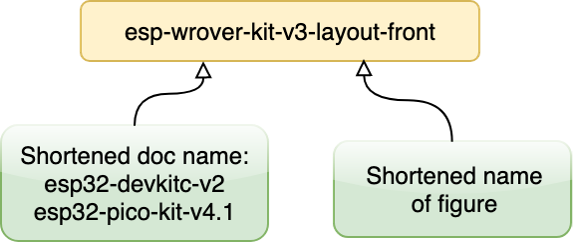
Add a label with a descriptive name immediately before the figure to which you want to refer. The recommended naming pattern for a label is as follows:
Picture-file-name.If the label will also be used to refer to this figure from other documents, use the pattern
Shortened-doc-name-picture-file-name.
Place the
:ref:role with this label name where you need a link to this figure.
An example of an established style for adding links to a figure in reST documents is given below:
.. figure:: ../../_static/esp32-devkitc-functional-overview.jpg
    :align: center
    :alt: ESP32-DevKitC V4 with ESP-WROOM-32 module soldered

    ESP32-DevKitC V4 with an ESP-WROOM-32 module

For description of components, see :ref:`ESP32-DevKitC V4 board <get-started-esp32-devkitc-functional-overview>`.